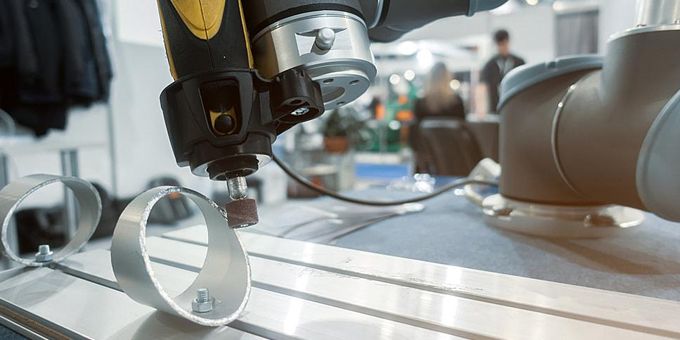
The nature of the deburring task is highly repetitive, dirty, and carries a risk of injury. Retaining personnel for such a strenuous and messy is challenging. Robotic deburring is an appealing option for these reasons, plus the results are more precise and repeatable.
 Choosing a Robotic Spindle for Deburring

Mark Fairchild | Precision Drive Systems
Robotics integrators are finding an increasing need for robotic deburring systems, and for good reasons. Deburring is necessary for various fabricating operations, but attracting and retaining employees to perform the work is difficult. Labor shortages are ongoing, and the National Association of Manufacturers reported that in 2022 there were 800,000 unfilled manufacturing jobs in the U.S., with 2.1 million predicted by 2030. The nature of the deburring task is highly repetitive, dirty, and carries a risk of injury. Retaining personnel for such a strenuous, messy, and uninteresting job is challenging. Robotic deburring is an appealing option for these reasons, plus the results are more precise and repeatable.
Choosing the appropriate spindle for deburring applications carries a number of different considerations than for a milling assignment. In this article, we examine various aspects of spindle choice for deburring. We also examine polishing and sanding, which have slightly different requirements yet again.
From Where Is the Compliant Pressure Controlled?
Kenny Wilson, a Precision Drive Systems Engineering Manager with more than 25 years of experience, pointed out that the first thing to determine is whether the pressure applied to the workpiece will be controlled by the robot arm or the spindle itself.
A variety of active force compliant spindles are available that are closed-loop systems capable of maintaining a constant pressure regardless of orientation. That is, the spindle will compensate for the force of gravity to maintain the same pressure in all positions. Less expensive passive systems can be appropriate in applications where gravity is not a factor.
If the spindle is not controlling the pressure, then the robot arm must do it.
Either way, knowing this is the first step in choosing your spindle.
Bring the Part to the Spindle - or the Spindle to the Part
Wilson said that he's seen more and more cases in which the robotic deburring operation will be performed by keeping the spindle in a fixed position, and having the robot arm bring the part to the spindle. The advantages to this approach are several.
With a stationary spindle, the deburring system designer or specifying engineer can choose a large and powerful spindle without having to worry about a robot arm strong enough to carry it. Since the robot only needs to bring the relatively lightweight part to the spindle, the arm needn't be as robust as it would be if it had to manipulate a heavy spindle. The result is a less expensive system and potentially a lower maintenance solution.
However, some part geometries do not lend themselves well to being deburred using a stationary spindle. If the robot arm must carry the spindle, then it's important to choose a spindle that is powerful enough. The extra weight of the spindle will require a larger and stronger robot arm, thus adding cost to the system.
What are the Speed and Torque Requirements?
Wilson described a variety of considerations relating to speed and torque when choosing a spindle for deburring, buffing, and sanding.
"For a deburring application, you need a spindle that can handle both radial and axial loads," Wilson said. Usually, a standard set of bearings in the spindle will suffice, unlike in a milling application, in which a triplex or quad set of bearings may be needed. "For deburring, it's more about the speed and torque of the spindle than it is the bearings," Wilson explained. He went on to say that the spindle for a deburring task will probably need a higher speed and torque than a milling application. Whereas a milling application will need a lot of torque at a relatively low speed, a deburring application will require a substantial torque at a higher speed.
Sanding, deburring, and buffing each have unique requirements as it relates to the physics of the spindle. Deburring is usually high-speed while buffing will use a little lower speed. Polishing will often need more torque at a lower speed than deburring.
In a sanding application, Wilson said the angle at which the sanding wheel will contact the workpiece - and the percentage of the wheel that will make contact - need to be known. Combining these factors with the force applied enables one to calculate the torque requirements of the spindle.
Conclusion
Choosing a spindle for a deburring application should be done carefully to achieve a system that is both cost-effective and will produce the desired results. Calculating the speed and torque requirements of the spindle requires knowledge of many different aspects of the application. A robotic integrator can take advantage of the expertise and experience of spindle experts to help in making the best choice.
About Precision Drive Systems
Since 1996, PDS has been the global leader in providing new spindles, design and engineering, customer support, and repairs for spindle applications in fabricating metal, wood, plastics, stone, marble, glass, and robotics manufacturing industries. The PDS corporate office is located near Charlotte in Bessemer City, NC. European customers are provided local solutions by the PDS service facility in Herford, Germany, with affiliated offices located worldwide. For more information, visit www.SpindleRepair.com or call 704-922-1206.
The content & opinions in this article are the author’s and do not necessarily represent the views of RoboticsTomorrow
Comments (0)
This post does not have any comments. Be the first to leave a comment below.
Featured Product

