Basic considerations at the beginning of assembling a cable management system can prevent costly problems later on, such as a loss of continuity, insulation damage, mechanical deformation, or EMI problems.
 7 Cable Management Mistakes to Avoid

Don Nester | igus Inc.
One of the most common problems that engineers encounter when using a cable management system is downtime. Downtime refers to periods of time when a system is unavailable, therefore causing that system to fail to provide or perform its primary function.
To prevent unnecessary downtime, your cable management system should be correctly specified, designed, and installed by knowledgeable experts. Basic considerations at the beginning of assembling a cable management system can prevent costly problems later on, such as a loss of continuity, insulation damage, mechanical deformation, or EMI problems.
Nowadays, cable carriers can withstand longer travels, faster speeds, and heavier loads which further increases the risk of cable failure during operation. Old industry rules of thumb, such as only filling up to 80% of a cable carrier’s cross section, have become outdated and ineffective in combating this. Luckily, advances in automation technology such as the rising use of smart plastics and the industrial internet of things (IIOT), makes it easier than ever before to detect and prevent operation failures before they occur.
We have compiled a list of the 7 most common cable management mistakes, and what you can do to avoid making these mistakes in order to prevent downtime in your application.
1. Lack of interior separation

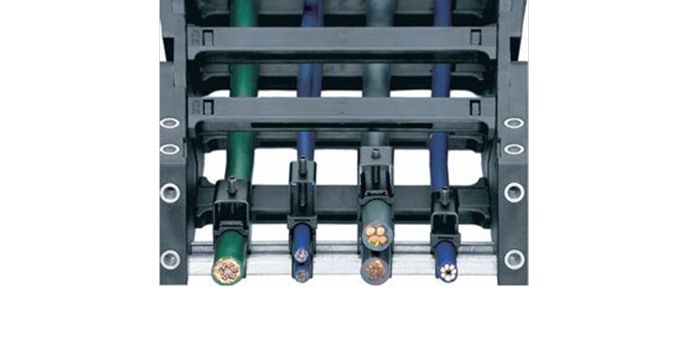
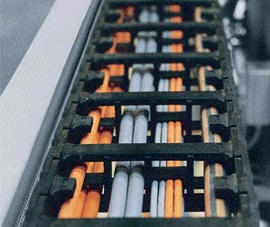
Interior separators and shelves are crucial for keeping similar cables and hoses compartmentalized. When no separation is used, cables can cross over one another and become tangled.
The clearance height of a compartment with several cables and hoses shouldn’t amount to more than 1.5 times the diameter of the largest cable or hose. Cables with wide differences in diameter should be laid in separate compartments. Cables and hoses with incompatible jackets should also be separated. (See #6 below for more on this.)
The maximum cable or hose diameter corresponds to the inner height of the selected cable carrier, with additional minimum clearance. We recommend leaving a 10% clearance surrounding electrical cables, and a 20% clearance surrounding hydraulic hoses.
The faster and more frequently a cable carrier operates, the more important the exact positioning of the cables and hoses inside. For high-speed applications over 1.64 feet per second, or high-cycle applications with over 10,000 cycles per year, cables or hoses must not be laid on top of one another without horizontal separation.
2. Uneven distribution of weight
Cables and hoses need to be laid inside a cable carrier so that they are able to move freely without exerting tensile forces along the radius. Unevenly distributed weight can result in a cable carrier that is too heavy on one side, which can disrupt movement and cause the carrier to tilt, potentially interfering with the work area.
3. Overfilled cable carrier

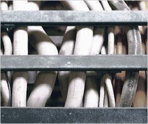
While it may be hard to leave seemingly available cable carrier space unfilled, overfilling a cable carrier can obstruct free movement. Cables that do not have room to move properly will interfere with the movement of the cable carrier.
Additionally, if cables become caught on one another and bind, jacket abrasion can be significantly increased. There is also a greater chance of electromagnetic interference, or EMI, when power and data cables are positioned close together.
As a rule, we recommend you space all power and data cables as far apart as possible in order to best prevent EMI.
4. Lack of proper strain relief
As the cable carrier moves back and forth, the cable will pull into the carrier and bunch up, causing premature system failure. Points outside the carrier, such as connectors or end termination points, will also absorb all the mechanical forces.
Typically, round electrical cables should be secured with strain relief at both ends. In exceptional cases, the cables may be fixed with strain relief at the moving end only. A gap of 10-30 times the cable diameter between the end of the bend radius and the fixed point is recommended.
5. Cables installed along the neutral axis
Cables with proper strain relief should be positioned in the neutral axis of a cable carrier. The cables should not be pulled tight against the inner radius or pushed up against the outer radius.
Strain relief should be properly installed, and then tested in both the extended and the home position.
6. Different jacket types placed next to each other
If the outer jacket of cables/hoses have different coefficients of friction and rub against one another, the harder, more resilient material will gradually wear down the softer jacket leading to cable failure.
While PUR and TPE jackets have similar wear characteristics and laying these types of cables together is not a problem, mixing PVC and PUR jackets is not recommended. If jacket materials need to be mixed in the same carrier, then ensure that jacket materials are rated for cable carrier use. Rubber or thermoset jacket materials tend to have tackier surfaces and will bind inside cable carriers, and are therefore not recommended as outer jacket materials when using a cable carrier system.
7. Incorrect cable carrier length
If the cable carrier’s length is miscalculated, then the full range of movement could be compromised. Pulled or stretched cables can result in conductor breakage.
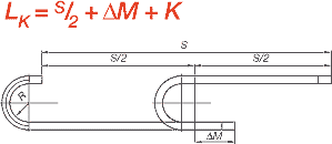
To properly calculate the length of an energy chain cable carrier, use the following equations:
LK = S/2 + K or LK = S/2 + ΔM + K
 If the fixed end is located in the center of travel, the cable carrier’s length, “LK,” is calculated by using half the length of travel, and adding the value “K” for the bend radius. Placing the fixed end in the center of travel is the most cost-effective solution, as it requires the shortest possible cable carrier and cable/hose lengths. When the fixed end is not located in the center, the offset mounting value (ΔM) must be added.
The content & opinions in this article are the author’s and do not necessarily represent the views of RoboticsTomorrow

igus
The mission of igus® is to use its innovative polymer materials to develop products that provide creative solutions and exceed our customers' expectations while delivering fast, accurate service.
Other Articles
Low-Cost Robotics Elevate Industrial Inspection Processes
New Exoskeleton is Revolutionizing Work Processes
The Less is More Approach to Robotic Cable Management
More about igus
Comments (0)
This post does not have any comments. Be the first to leave a comment below.
Featured Product

