A general in depth analysis shows that the highest encoder resolutions are required for very precise speed control. The encoder resolution increases with the square of the demanded speed accuracy.
Encoder Selection: Speed Control
Urs Kafader | maxon motor
Reprinted with permission from maxon motor’s drive.tech blog
A general in depth analysis shows that the highest encoder resolutions are required for very precise speed control. The encoder resolution increases with the square of the demanded speed accuracy. In addition, a fast speed control loop is needed and a high mass inertia has a beneficial effect on speed stability.
- Keep in mind: It’s not only the resolution of the encoder that influences accurate and dynamic speed control. It’s the reaction of the system as a whole. The response time may be limited by current and voltage constraints of power supply and controller, by the sampling rate of the control loop, by mass inertias, friction variation and mechanical play.
How does speed evaluation with incremental encoders work?
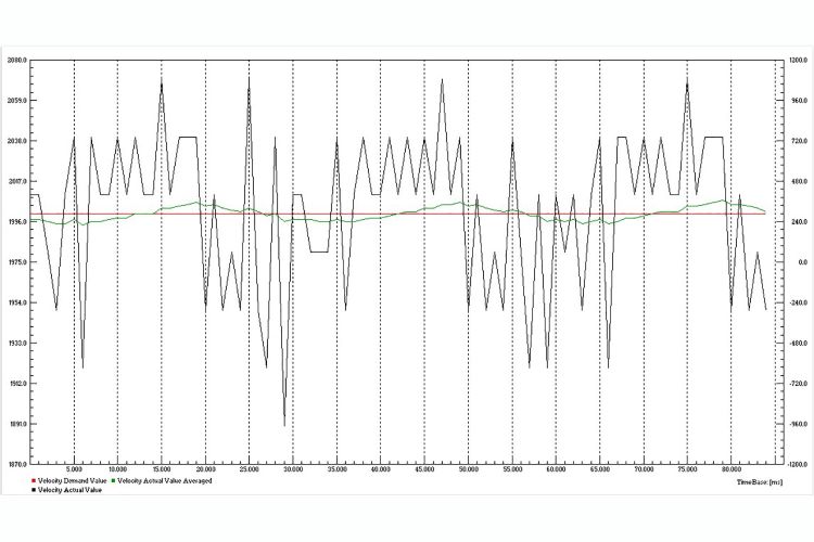
The speed is evaluated in the controller by counting the number of state changes within a given time interval. An EPOS2 for example, has a speed controller sampling rate of 1 kHz. Therefore, the internal speed is measured in integers of quadcounts per ms (qc/ms) corresponding to a speed resolution of 30 rpm on a 500 cpt encoder (2000 qc per turn). The lower the encoder resolution, the higher this speed quantization.
It must be emphasized that this is a metrology problem due to the digital acquisition. What you measure in not how the system behaves. The actual speed of the motor will assume the set value, and will maintain it because of the mechanical inertia (flywheel effect). It’s just the measured values that fluctuate around the average speed.

Speed control at high speeds
The electronic components of the encoder limit the maximum pulse frequency that can be handled and, therefore, restricting the maximum speed of the encoder. In some cases, this restriction stems from mechanical considerations such as unbalance and mounting tolerances.
The frequency constraints at the encoder input on the controller side should also be considered. If very high speeds are required, a correspondingly low encoder resolution must be chosen.
A relative speed variation of a few percent at high speeds of several thousand rpm corresponds to several 10 rpm absolute accuracy and is quite easy to achieve.
Rule #4: Encoder for High Speed Control (> 500 rpm)
Select encoder with a moderate or low number of states and a sufficiently high maximum speed rating. In many cases, the maxon EASY encoder is the perfect solution. There is usually no need for a high precision optical encoder. Rule of thumb: (speed in rpm) x (encoder resolution in cpt) > 100’000 rpm cpt is sufficient by far for most applications.

Speed control at low speeds
While the state counting type of speed evaluation results in a good speed control at high speeds, it becomes difficult at very low speed. Imagine a speed of 60 rpm, that’s 1 turn per second to be maintained with an accuracy of 5% or 3rpm. With the same 500 cpt encoder and 1ms control cycle time as above, you will never be able to get a stable and smoothly controlled speed.
In order to reduce the absolute speed variation, you need a higher encoder resolution and a faster controller. Just imagine an encoder with 5000 cpt in the situation described above; you get 10 times more feedback. However, at low speeds also the control loop should be able to react faster for keeping the absolute speed deviation small. Both requirements increase the demands on the encoder. The encoder resolution increases with the square of the absolute speed stability: Half the permitted speed variation require a 4 times higher encoder resolution.
At very low speeds, some controller allow an alternative way of speed evaluation. It measures the time that elapses between 2 states. The speed feedback values will be more homogeneous, allowing a stiffer and more dynamic control.
The EPOS4 controller allows the use of another method at low speeds, called speed observer. The speed observer is an element in the control loop. It calculates the observed speed in two steps. First, the speed, position and external torque is predicted based on the parameters that define the mechanical transfer function of the system. Second, the predicted values are corrected based on the newly measured rotor position.
But still, an encoder with a high resolution and a fast controller are advantageous.
Rule #5: Encoder for Low Speed Control (< 100 rpm)
Select encoder with a high or very high number of states in combination with a fast controller.
The content & opinions in this article are the author’s and do not necessarily represent the views of RoboticsTomorrow

maxon group
maxon is a leading supplier of high-precision DC brush and brushless servo motors and drives. These motors range in size from 4 - 90 mm and are available up to 500 watts. We combine electric motors, gears and DC motor controls into high-precision, intelligent drive systems that can be custom-made to fit the specific needs of customer applications.
Other Articles
Understanding Torque and Speed in Electric Motors
How Parvalux Is Helping to Develop the Next Generation of Conveyor Systems
Robots speeding up material handling
More about maxon group
Comments (0)
This post does not have any comments. Be the first to leave a comment below.
Featured Product

