Whether a robot is needed to prototype a part or a robot is the object being prototyped, Rapid Prototyping is the future.
Len Calderone for | RoboticsTomorrow
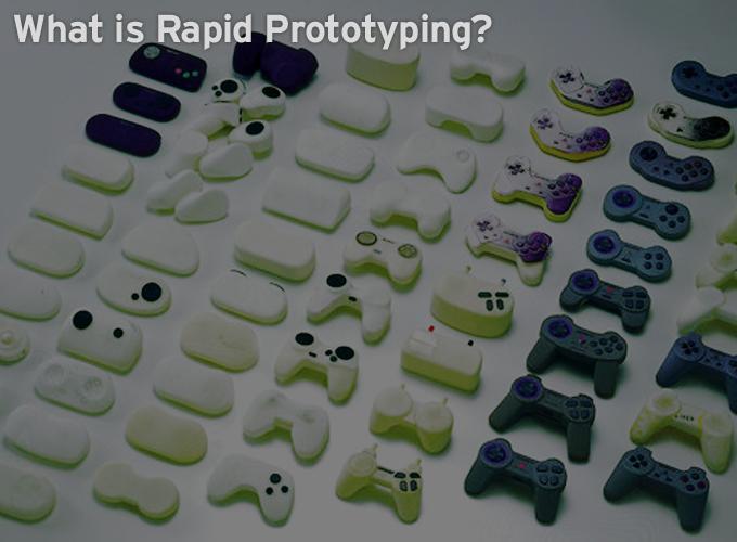
Prototyping is the process of using visuals to illustrate what would take thousands of words’ worth of design and development specifications that detail how a device would behave and look. Rapid Prototyping is the technique used to quickly fabricate a model of a physical part or assembly using three-dimensional computer aided design (CAD) data.
One type of Rapid Prototyping is known as 3D printing, which is an additive manufacturing technology. The process begins with taking a virtual design from modeling or CAD software. The 3D printing machine reads the data from the CAD drawing and lays down successive layers of liquid, powder, or sheet material, and builds up the physical model from a series of cross sections. These layers, which correspond to the virtual cross section from the CAD model, are automatically joined together to create the final shape.
Rapid Prototyping uses a standard data interface, implemented as the STL file format, to translate from the CAD software to the 3D prototyping machine. The STL file approximates the shape of a part or assembly using triangular facets. Typically, Rapid Prototyping systems can produce 3D models within a few hours. Yet, this can vary widely, depending on the type of machine being used and the size and number of models being produced.
When complex interactions, new functionality, technology or design changes are necessary, Rapid Prototyping comes into play. The objective of Rapid Prototyping is to review how a part will work or what the design will look like without prototyping the entire product.
Designing a part is one thing, while designing a tool to make the part is another. Rapid Prototyping helps to analyze the form, fit, and function of a part before expensive tooling is purchased. It also optimizes the manufacturability of a design to lessen production costs. Rapid prototyping increases quality and drives costs down, getting a product to market faster by assuring that the production tool is right the first time.
New to 3-D printing is a material from Stratasys called PolyJet photopolymers that simulate the appearance and functionality of polypropylene. PolyJet photopolymers combine a wide variety of material properties with thin layers, so that true product realism can be produced in prototypes.
The Stratasys Objet 3D Printers are the only additive manufacturing systems in the world than give you multi-material flexibility. Materials can be combined within the same 3D printed model or in the same print job. Two materials can be combined during printing process to create composite digital materials with very specific properties. Using more than 100 material combinations, precise characteristics can be simulated so that prototypes match the look, feel and function of the most complex end products. Each of the 100-plus digital materials is based on various combinations of the 17 primary PolyJet photopolymers. A single prototype can contain as many as 14 distinct material properties, all created in one build process
One advanced simulated polypropylene material is Endur, which offers durability and an attractive surface finish. It can be used to quickly build tough prototypes for snap-fit components, hinges and other demanding applications. Endur is engineered to deliver reliable build performance inside the 3D printer, as well as great-performing prototypes with impressive dimensional stability outside of the 3D printer. It comes in a bright, true white with PolyJet technology’s signature fine resolution and smooth curves.
Sometimes you can learn something important in a few minutes from a prototype that might have taken weeks or months otherwise. Mechanical design seems to require repetition, so, the faster you can repeat a process, especially at the beginning of a project, the better. One of the most common goals of prototyping is to demonstrate a concept or proposal. Usually the complexity of a prototype varies with the complexity of an idea.
Currently, there are over 30 different types of Rapid Prototyping processes in existence. Some of these are commercially available while others are still in the development stage. Major improvements in the overall quality of prototyped parts are being accomplished through enhancements in printer precision, materials, material durability, part throughput, and surface consistency. These improvements are leading to the progression of the functionality of Rapid Prototyping prototypes.
A proposed robot design should be evaluated prior to full prototyping to ensure the most expeditious and cost effective changes in the design. CAD software packages are now being used, but this type of a software package cannot provide a working 3-D model with realistic features. There is also a requirement for developing methodologies and techniques that will allow fast design, fabrication and testing of robotic and other multi-articulated mechanical systems.
Using Rapid Prototyping, physical prototypes of the robot that is being designed can be achieved in a very short time, thus making quick design evaluation possible. And the properties of the robot evaluated immediately. Rapid Prototyping makes the incorporation and attachment of sensors, actuators and transmission elements within the robot easier, including one step fabrication of multi-articulated, multi-link systems as a whole, without requiring assembly of its structural members and joints after fabrication. The construction of robots can drastically change using a one-step fabrication technique.
To reduce prototyping time, there is a need to automate the production of just one component for development and evaluation. Casting, which may be used to make such a component, is an expensive and time consuming process. Most of the Rapid Prototyping processes evolved in response to this requirement using resin based materials, which are not always suitable for the purpose of testing. Metal based prototypes are often required, and additional processing is necessary to convert resin based materials to a useful form.
In Rapid Prototyping, using fusion welding, the component is formed by melting and depositing the metal using the GMA welding process. A CAD drawing system is used to create the initial solid shape and a welding robot is used to manipulate the welding torch. Using the CAD drawing, a slicing add-on of the program is implemented to produce the desired layers for the robotic program. The welding parameters are automatically generated by the program in order to achieve the required bead geometry and stable operating parameters. The robotic program may be modified if necessary, and then compiled and downloaded to the robot.
To build a component using the gas metal arc welding process, the robot has to bond a number of layers of metal on top of each other. The location of these layers needs to be mathematically defined by the CAD program to allow the robot to follow them during the building procedure. The weld deposited has some thickness and the path the robot has to follow is the center line of the weld. The individual weld runs are considered to be ‘slices’ of the initial CAD solid. This is similar to 3-D printing, except sold material is welded together.
Whether a robot is needed to prototype a part or a robot is the object being prototyped, Rapid Prototyping is the future. The concept of a Rapid Prototyping machine is no longer science fantasy with the next step forward being mass manufacturing using this technology.
For additional information:
- http://www.stratasys.com/~/media/Main/Files/White%20Papers/SSYS-WP-SSYS-InHouseVsOutsource-1-14.pdf
- http://www.stratasys.com/~/media/Main/Secure/White%20Papers/Rebranded/SSYS-WP-JustifyingtheCostofanRPSystem-03-13.pdf
- http://www.kluzinternational.com/wp-content/uploads/2012/01/SubtractiveRapidPrototyping_WhitePaper_Roland2011.pdf
- http://malcodesignanddelivergroup.wordpress.com/2013/10/25/new-malco-d2-white-paper-eight-common-mistakes-in-rapid-prototyping/
- http://www.phillipsmedisize.com/sites/default/files/whitepaper/Prototyping%20White%20Paper.pdf
The content & opinions in this article are the author’s and do not necessarily represent the views of RoboticsTomorrow
Comments (0)
This post does not have any comments. Be the first to leave a comment below.
Featured Product


