Designing curvilinear guide or actuator systems can be more difficult than designing linear ones. However, installing such systems can improve payload transportation and handling simplicity and efficiency.
Leslie Lui, Mechanical Design Engineer | Bishop-Wisecarver Corporation
Introduction
In this white paper, we will discuss the topic of guide-wheel based ring and track systems. In today's market there are more compact offerings available with better positioning accuracy and customizable options for cargo carrying positions than alternative conveyor systems for curvilinear applications.
In the ongoing drive to reduce production costs, one trend at manufacturing facilities is grouping production work stations as closely as possible to minimize material movement and to conserve valuable floor space. Doing this means that materials have to move along increasingly complex curvilinear paths. Most commercially-available guide and actuator systems are linear designs and can’t easily handle non-linear paths. However, curvilinear guide and actuator systems, such as guide-wheel based ring and track systems, are available for such situations.
Ring and Track Systems
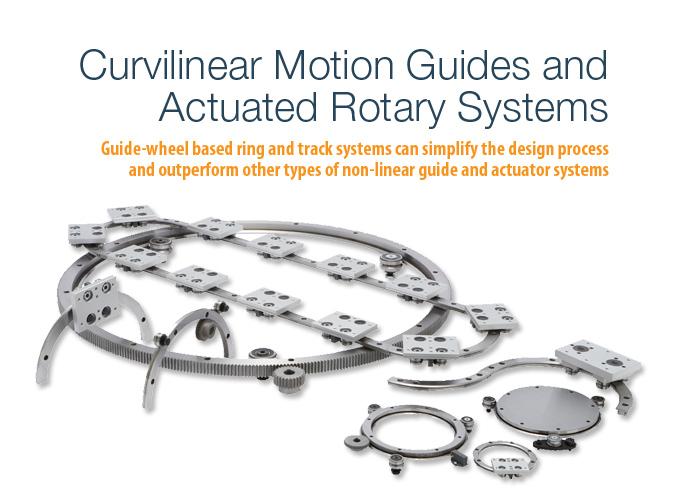
At the heart of guide-wheel based ring and track systems are vee groove bearing guide wheels and vee edge slides. The wheels and slides have complementary vee profile running surfaces which let guide-wheel equipped carriages run smoothly along slides while resisting lateral or rotational movement, even under high applied loads.
Carriages can follow straight or circular paths through the use of straight and ring slide segments, or complex, curvilinear paths through a combination of straight and ring slide segments. In rotary motion applications, it’s possible for the wheels to be statically mounted and the ring slides rotated relative to them. Some curvilinear guide systems can also be converted into an actuated system with the addition of components such as carriage linkages, drive elements, and motors.
Guide-wheel ring and straight slides come in many profile sizes to accommodate wheels of various sizes and load capacities. Straight slides also come in different lengths and ring slides are available with various curvature radii and angular spans. Some ring slides are available with hollow or solid centers, also called ring disks. Other slide options can include different vee configurations and integrated racks for actuation by pinion gears.
Guide-wheel based ring and track system designs make them among the most contamination and corrosion-resistant options available. Guide wheels usually contain enough lubrication to last their expected running lives, have permanent seals to minimize lubrication loss and ingress of debris. The system components have simple shapes that don’t trap debris and many are made of stainless steel for added corrosion resistance.
Traditional Curvilinear Solutions
Traditional ways of accommodating curvilinear guide and actuator designs include conveyor systems and slewing rings. A belt conveyor system is the simplest type of conveyor and typically contains wide belts wrapped around cylindrical rollers in a frame. Motors rotate the rollers, which cause the belts to transport payload resting on top of them. While simpler belt conveyor systems can only move payloads in straight lines, curvilinear paths can be created by mounting multiple straight conveyors in series at offset angles along the desired path, or by using belts with interlinked pivoting segments, such as luggage conveyors at airports.
A roller conveyor system is similar to a belt version, except the wide belt is replaced by a series of closely-spaced rollers mounted in a framing system configured to follow a specified curvilinear path. Roller conveyor systems can be powered with motors coupled to the rollers directly or by intermediate drive belts, or un-powered, with payload moved by gravity or by hand.
Overhead trolley systems consist of curvilinear path track systems mounted high above the floor, with wheeled carriages that hang their payload underneath. Overhead trolley system carriages can be moved by hand or pulled by motor-driven chains running along the track. Slewing rings (also called turntable bearings) are essentially large machine bearings that use large quantities of small rolling elements. This enables them to maintain high load capacities while providing large bore IDs and thin profile races. Slewing rings can have gear racks machined into their races for direct driving.
How Ring and Track Systems Stack Up
Guide wheel-based ring and track systems can offer better positioning accuracy and precision than conveyor systems, a difference that can be important in applications where the payload is fragile or must be held rigidly and accurately positioned for processing while being moved through the system. The wheels in guide wheel-based ring and track systems are designed to be firmly preloaded against the slide, preventing the carriage from shifting in any direction other than along the intended travel path. This level of positioning accuracy generally isn’t possible in conveyor systems, where payload is primarily constrained to the moving elements by gravity.
Belt and roller conveyor systems provide no horizontal constraint and can require side guide rails to prevent payload from falling off the sides of the moving elements. The payload can be subject to continuous vibrations because it’s constantly being transferred from one roller or belt loop to another, and can get tangled with conveyor system components if they have incompatible shapes, causing irregular flow rates, collisions, and jams. Overhead trolley system carriages only have enough horizontal constraint to keep from falling off the track and generally use non-rigid linkages such as chains or hooks to carry payload, allowing them to swing freely and possibly hit other objects.
Conveyor systems’ reliance on gravity for constraining payload also limits the possible positions where the payload can be carried and the ability to move payload vertically. Belt and roller conveyor systems must carry their payload directly over their moving elements and can’t transport them up or down steep inclines. Overhead trolley system carriages must have their payload hanging directly under them for stability and cannot move up or down steep sections since the hanging payload can contact the track or payload on adjacent carriages. However, in a guide-wheel based ring and track system, payload can be securely mounted at any position relative to the carriage. The payload can also be transported in any direction, regardless of gravity, since the carriage wheels are firmly constrained against the slides and only permit movement along the designated path.
Guide-wheel based ring and track systems can require less space, support structure, and maintenance than other conveyor systems. With proper mounting fixtures attached, the carriages can carry payload much wider than themselves. This allows these systems and their support structure to be more compact than belt and roller conveyor systems, whose rolling elements have to be wider than their intended payload. Overhead trolleys can carry relatively wide payload but require sizeable, sturdy support structures because their track systems have to be elevated high enough for their underhung payload to be accessible and clear of any ground level obstacles. The relatively large size of support structures for conveyor systems also makes them the most difficult and expensive to assemble and reconfigure. Conveyor systems are also more difficult to keep clean than guide wheel-based ring and track systems since their components are larger, more numerous, and have complex shapes that trap debris more easily. Slewing rings are better suited than conveyor systems for applications requiring only circular motion because they can be more compact, lightweight, and are available in fully assembled individual units that can be faster to incorporate into an application. They also offer better accuracy and smoothness, and can have payload mounted to them, like guide-wheel based systems, but still have some disadvantages compared to the latter.
While guide-wheel based track rotary systems and slewing rings can have similar ease of assembly, the former can be easier to service due to the components being interchangeable. Slewing rings are generally fully assembled at the factory due to the precise assembly and machining required for smooth and accurate performance. The entire ring usually must be replaced if even one component fails, making them difficult to service in the field. Since slewing rings are sometimes the primary mounting structure for application components, replacement of a slewing ring can also require reassembling everything mounted to it.
For guide-wheel based rotary systems, only the damaged components need to be replaced because their common fit design permits individual components to be assembled and used in any compatible system, not just a particular unit of suitable, matched fit like slewing rings. It’s also possible in some applications to replace damaged components in guide-wheel based track systems without disassembling any other components.
Slewing rings can offer better rigidity and smoothness than conveyor systems, but are generally not preloaded. Preloading the rolling elements for better rigidity and smoothness is common in smaller machine bearings, but rare in slewing rings since large components are harder to precisely machine and their form and fit are more affected by external factors. Small manufacturing flaws, component deformation due to external loads or uneven mounting surfaces, or uneven thermal expansion due to large temperature variations between components are more likely to affect preload in larger bearings like slewing rings.
Preload changes can result in internal component clearance, which reduces system rigidity, or high interference which makes rotation more difficult and damages components. A slewing ring’s preload level depends on internal component dimensions and can’t be adjusted after assembly. External factors such as uneven mounting surfaces and thermal expansion can also change the preload in guide wheel-based rotary systems. However, they’re less of an issue since the preload is set during assembly in an application and can be easily adjusted afterward.
Guide-wheel based ring slides can have a significant size advantage over slewing rings in applications requiring less than 360° of travel. Slewing rings must be fully circular to provide complete travel circuits for their rolling elements, even if the application requires far less than 360° of travel. In guide-wheel based rotary systems the ring slide segment arc length only needs to be long enough to support all guide wheels (which can be as few as three) throughout the full arc of travel.
Designing curvilinear guide or actuator systems can be more difficult than designing linear ones. However, installing such systems can improve payload transportation and handling simplicity and efficiency. Guide-wheel based ring and track systems can simplify the design process and outperform other types of non-linear guide and actuator systems.
 About Bishop-Wisecarver
Bishop-Wisecarver Corporation, a Bishop-Wisecarver Group company, helps manufacturers and automation solution providers engineer linear and rotary motion products. With 60+ years of engineering expertise and manufacturing best practices working with over 20,000 customers, we understand our customers’ design and application requirements which enables us to develop unique solutions that ship within 2 to 3 weeks. Customers achieve 50% faster time to market, up to 50-75% lower maintenance and installed costs, product differentiation and longer product life.
Our product line includes quality components and accessories, manual linear guide systems, actuated linear guide systems and rotary guides and systems. Stainless steel, high temperature, washdown and clean room-compatible products are among Bishop-Wisecarver's more recent product introductions. Our more popular offerings include the following trade names: DualVee, LoPro, UtiliTrak, MadeWell and GV3.
The content & opinions in this article are the author’s and do not necessarily represent the views of RoboticsTomorrow
Comments (0)
This post does not have any comments. Be the first to leave a comment below.
Featured Product


