The circuitry to sense precisely the current of three windings of a motor adds a significant space and cost to an electronic board. For that reason, new control algorithms are being developed to work with only one shunt.
Precise Brushless Torque Control With Only 1 Shunt Resistor
Contributed by | Ingenia Motion Control
State of the art
Sinusoidal permanent magnet motors also known as brushless motors (BLDC) are becoming popular nowadays and replacing brushed DC in a variety of applications. The main reasons are that they achieve higher efficiencies, with lower inertias and require less maintenance due to the elimination of the brushes.
As brushless motors are not self-commutated, an electronic board for commutation control is always necessary which increase the cost and the space of the overall system. The lines of investigations in motor control discipline try to improve system efficiency while reducing the cost of electronics.
Actually there are different techniques for controlling the torque generated by a brushless motor which include: Scalar, Trapezoidal or Field oriented control (FOC).
Scalar control does not reach high efficiency and high torque because it just rotates the magnetic field produced by the stator without taking into consideration the position of the rotor.
Trapezoidal control only applies current in two windings of the motor leaving the third one unconnected. When the motor turns, the used windings are switched progressively generating a total of six different magnetic field vectors. This control works well in many applications but it introduces a torque ripple due to the misaligned from the optimal direction, which also represents a loss in efficiency.
Field oriented control (FOC) provides smooth movement event at low speed as well as high efficient because it assures that the generated magnetic field vector is always orthogonal to the position of the rotor generating the maximum torque. However to implement FOC, the value of the currents passing through the three windings of the motor must be precisely known.
The circuitry to sense precisely the current of three windings of a motor adds a significant space and cost to an electronic board. For that reason, new control algorithms are being developed to work with only one shunt.
Ingenia has designed and successfully implemented a Field Oriented torque Control of a brushless motor using one shunt sensing circuitry obtaining an ultra-low cost but high performances device.
Topology of the inverter
Brushless motors normally use a three-phase inverter as shown below which allows controlling independently the current applied to each coil of the motor.
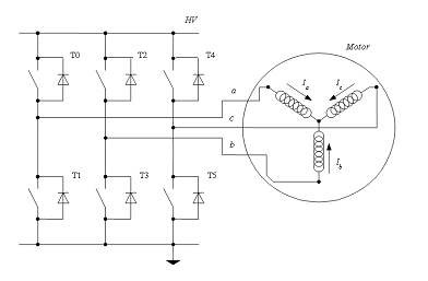
Three-phase inverter is composed by three legs, each one with two electronic switches (MOSFETs or IGBT) allowing the current to flow from and to the legs.
The electronic switches normally work only in saturation zone to improve the system efficiency, and uses Pulse-Width Modulation (PWM) techniques to control the amount of energy applied to the motor. The most common techniques used are sinusoidal modulation, third-harmonic injection and Space Vector Pulse Width Modulation (SVPWM).
The SVPWM technique implemented in this development increases the voltage utilization in about 15% compared to sinusoidal one and reduces the Total Harmonic Distortion (THD) compared to third-harmonic injection.
Current sensing
To perform a Field Oriented Control in a three phases motor the current passing through the winding must be known. Normally and using Kirchhoff law, sensing two phases is enough to know the value of the three winding currents.
There are mainly three different methods represented in Figure xx to sense the current passing through the windings of the motor:
- Directly measurement on the phase line by means of transformers, hall sensors or amplifiers with high common-mode rejection ratio. This approach has an easy implementation from hardware and firmware point of view but implies a high product cost due to the components used.
- Measurement on the low side of the half-bridge path. Putting a shunt resistor on the low side path generates a voltage drop proportional to the circulating current which could be amplified by standard operational amplifiers. The normal approach is to use three shunt resistors, one for each phase. However using Kirchhoff’s current law (the sum of currents in a network is zero), reading just two motor coils, the third one could be estimated. This approach reduces the price of the system as it could use only two low-cost sensing circuits but needs an ADC with simultaneous sampling capabilities.
- Measurement on the Bus voltage path. To reduce the number of current sensors and therefore the used space and overall cost of the design; the three-phase stator currents could measured by means of a single DC-Link current shunt sensor. This method has many advantages but needs a complex current reconstruction process. As the same conditioning system is used to sense the three phases, the gain and offset will be exactly the same, eliminating the need of a specific calibration process for each phase.
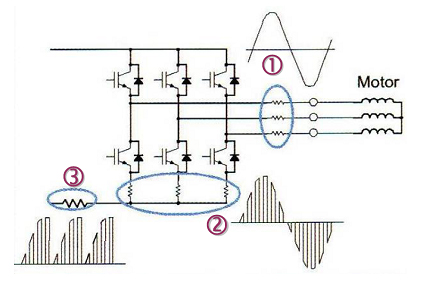
1-shunt sensing implementation
The 1-shunt algorithm senses the current two times per PWM cycle. Both samplings are executed in the middle of the space between PWM transitions as shown in the following figure (the sampling point is marked with an arrow). Depending on the active sector each sampling will correspond to a different motor coil. The third current could be obtained using Kirchhoff law.

The ADC senses the currents during the first half of the PWM period and also sensing some extra analog inputs (temperature, voltage monitoring, user analog input, etc.) during the second half.
This algorithm works well but cannot read the current in the following cases:
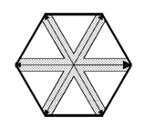
When the voltage vector is crossing a sector border. In this situations the length of the duties of the two phases are similar (or the current is not still stable) and therefore there is no space to sample the current between transitions.
When the modulation index is low. In this situations the length of the duties of the three phases are similar and therefore there is no space to sample the current between transitions.
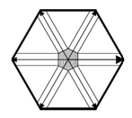
To overcome this problem the algorithm has been modified to generate an asymmetrical PWM assuring always a minimum time to perform the correct current sensing.
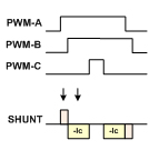
However this improvement has some limitations:
- A minimum voltage vector is always needed to perform a correct current sensing.
- The maximum bus utilization cannot be reached due to the asymmetrical PWM update. This will limit the maximum voltage utilization of the system.
Conclusions
Ingenia has designed and successfully implemented a Field Oriented torque Control of a brushless motor, using 1-shunt current sensing circuitry obtaining an ultra-low cost but high performances device.
A velocity and position control loops have been finally incorporated giving really advanced control features to the system. Moreover, a measurement of other analog inputs has been added giving some high-end protections to the board (i.e. over-temperature, over and under-voltage, etc.).
Below there is a list of the main benefits of this development:
- Precise torque control, high efficiency and low noise in large speed range thanks to the use of Field-oriented control.
- High cost reduction because only one sensing circuitry is used.
- Same gain and offset for the three current sensing, eliminating the need of a specific calibration process for each phase during production.
- Low physical space needed.
- Popular power-stage with common ground normally used for trapezoidal commutation could be used simplifying the design and reducing the cost.
 About Ingenia Motion Control
Ingenia is a leading motion control technology company specialized in the design, development and manufacture of motion control products and custom motion systems.
Ingenia motion control solutions include compact and high power density digital servo drives, motion control ICs and control software for several motor technologies including servo motors (DC brush and brushless), microstepping, and step motors. Advanced features include CAN (CANopen) bus, serial communications; 6 step and sinusoidal commutation; field oriented control; advanced PID filter with velocity and acceleration feed forward, and much more.
The content & opinions in this article are the author’s and do not necessarily represent the views of RoboticsTomorrow
Comments (0)
This post does not have any comments. Be the first to leave a comment below.
Featured Product

